A fuel tanker discharge system moves petroleum products from the trailer’s compartments into a receiving storage tank. It includes valves, piping, pumps, hoses, meters, and safety interlocks. The right setup depends on the product, the site, and the rules that govern the operation.
This article covers highway fuel tanker semi-trailers built to the U.S. DOT 406 spec (49 CFR 178.346). DOT 406 replaced the older MC 306 label after August 1995. The valve rules, shutoff requirements, inspection cycles, and vapor recovery points here follow that framework. DOT 407, DOT 412, and non-U.S. standards use different valve designs, pressure ratings, and test intervals. Those fall outside this scope.
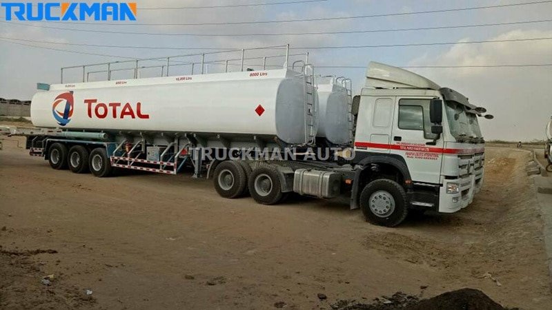
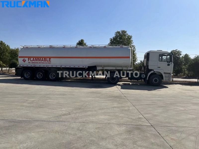
We design discharge systems as part of the full fuel tanker trailer. Every part ties back to how the operator delivers fuel. A gasoline tanker serving retail stations needs different discharge gear than a diesel tanker feeding industrial tanks. The flow rate, vapor recovery level, grounding setup, and valve sequence all shift. Each one changes with the product, the site, and the local rules.
Core Components of a DOT 406 Discharge System
Each part of a DOT 406 discharge assembly must match the product, compartment layout, and regulatory requirements. Picking from a generic parts list without checking these variables creates compliance gaps.
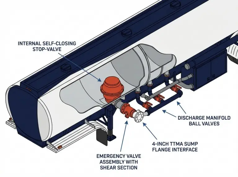
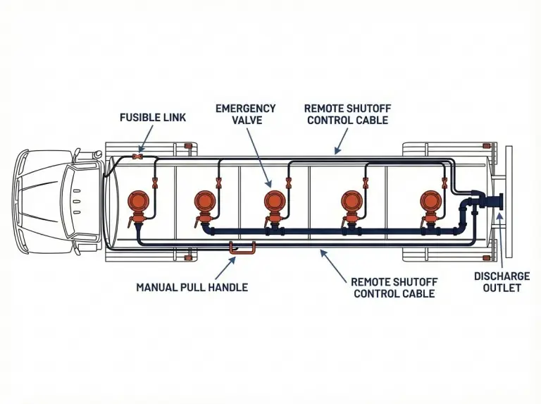
- Internal Self-Closing Stop-Valve:49 CFR 178.345-11 requires every loading/unloading outlet on a DOT 406 tank to have a self-closing stop-valve. This valve can sit inside the tank or outside, as close to the tank wall as possible. The system must close all outlets within 30 seconds in an emergency. The operator can trigger it from the cab, at the trailer, or through a heat-activated device in a fire. This 30-second limit is a federal ceiling, not a goal.
- Emergency Valve Assembly:This valve sits at the tank shell’s outlet nozzle. It has a shear section that breaks on impact before the tank wall or internal valve takes damage. Under 49 CFR 178.345-8, the shear section must break at no more than 70% of the load that would harm the valve or tank. It must sit within 4 inches of the tank shell radius or sump. Common setups include 90-degree elbow or straight body, 4-inch TTMA flange or Victaulic outlet, and manual or air-assisted trigger. The 4-inch TTMA sump is the standard interface in U.S. petroleum transport.
- Discharge Manifold:The manifold links bottom valves from each compartment to a shared outlet or separate lines. It uses ball valves or butterfly valves to direct flow. Bore size is 3-inch or 4-inch for most DOT 406 petroleum trailers. Pipe diameter sets the ceiling on flow rate. Valve count and layout control whether one or two compartments can drain at the same time.
- Discharge Hoses:Most setups use 3-inch or 4-inch ID hoses. Working pressures range from 50 to 150 psi, based on the pump and product. End-fittings must match the receiving site’s connection type. Cam-lock, dry-break, and API-type fittings are all common. The hose material must handle every product the trailer carries. This includes ethanol and biodiesel blends. Some rubber compounds break down under long exposure to higher biofuel levels.
- Overfill Prevention and Ground Check:Scully systems (or equal units) run continuous checks on grounding and overfill at each compartment. They link mainly to the loading terminal. But the wiring, sensors, and compartment ID tags must go in during the trailer build.
Gravity Discharge Versus Pump-Assisted Discharge
The choice depends on three factors. Where does the receiving tank sit? How fast must the operator offload? How thick is the product at working temperature? The wrong method leads to slow draining or wasted cost and weight. These decisions tie directly into the broader fuel tanker loading and unloading process, where discharge method sets the pace for the entire delivery stop.
Gravity Discharge: This method uses the height gap between the trailer and the receiving tank to push fuel down. At retail stations with underground tanks, the trailer outlet sits about 18 to 30 inches above grade. The tank top sits 4 to 8 feet below grade. That drop drives good flow for gasoline and diesel. Through a 4-inch system, gravity rates run from 300 to 600 GPM. The key factors are hose length, height gap, fuel thickness, and back-pressure from the receiving tank. As the trailer empties, the driving head drops. The last portion drains slower.
Pump-Assisted Discharge:A PTO-driven, hydraulic, or engine-driven pump adds mechanical force. PTO systems pull power from the tractor’s transmission. Gear and vane pumps (from makers like Blackmer and Roper) lead in petroleum use. They hold steady flow across a range of fuel types and self-prime well. Centrifugal pumps move more volume at low thickness but lose prime faster during final draining.
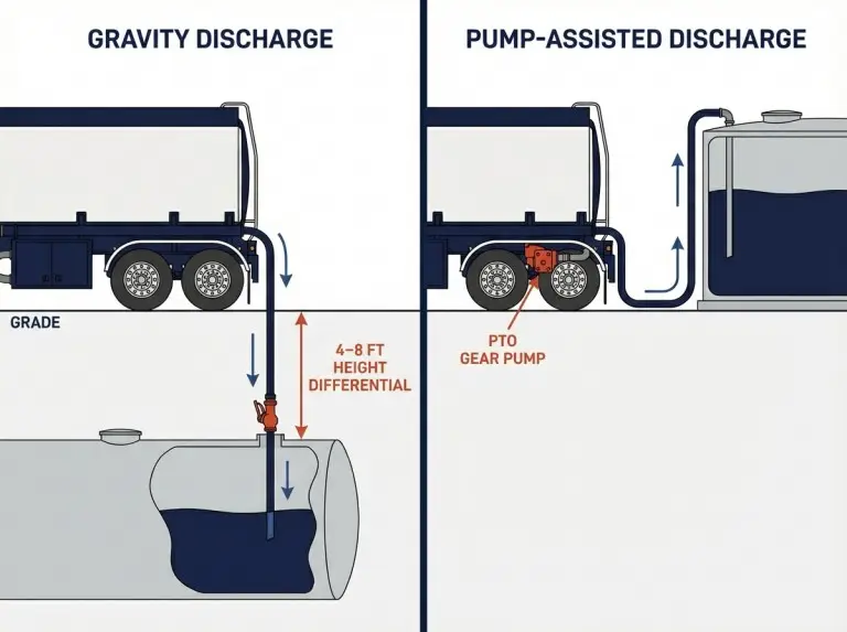
A pump becomes needed in three cases. The receiving tank sits at or above the trailer outlet. The site needs faster offloading. Or the product is too thick for gravity at working temperature. Standard PTO pump systems range from 150 to 450 GPM. Actual output depends on pipe size, hose run, height change, and fitting count.
For routes that mix underground and above-ground tanks, a combined gravity-and-pump setup gives the most range. The pump adds 200 to 425 pounds (pump, gearbox, mount). That weight cuts into legal payload. When teams pick a pump without checking each site first, they often get a mismatch. The pump wastes payload at easy sites or falls short at hard ones.
Why Discharge Rate Is Not Just a Pump Spec?
Flow rate depends on the tightest point in the whole path, not the pump rating. A bigger pump will not fix a bottleneck downstream.
The real limit comes from valve bore, manifold size, and elbow count. Each 90-degree turn adds drag. Hose bore, hose length, height gap, and receiving tank back-pressure also factor in. Consider a 450 GPM pump pushing through a 3-inch manifold, two elbows, and 50 feet of 3-inch hose. It will fall well short of its rating. Adding pump capacity without fixing the tight spot just raises pressure with little gain in flow.
Leftover product after discharge is another trouble spot. Operators often blame the pump. The real cause is usually tank shape. Flat compartments with poor slope toward the outlet hold more fuel than compartments with a designed sump and proper grade. The sump follows the 4-inch TTMA footprint for standard valve fitment. Slope angle, sump depth, and baffle layout are among the key design factors in fuel tanker trailer engineering that directly shape discharge performance.
When operators report fuel left after discharge, we trace it to one of three causes. First, not enough slope in the compartment. Second, the valve sits above the true low point. Third, air gets into the line and breaks pump prime before the tank is empty. Fixing these during design works far better than swapping the pump later. This matters most with mixed products. Diesel at cold temps drains much slower than gasoline.
Valve Layout and Emergency Shutoff Under DOT 406
Valve layout on a DOT 406 trailer must meet both flow needs and the safety rules in 49 CFR. The right setup depends on compartment count and product type.
Each compartment outlet needs its own self-closing stop-valve or an external valve with crash protection per 49 CFR 178.345-8. For standard petroleum fuels (non-corrosive service), the remote shutoff must work by manual or mechanical means. In a fire, it must also close through a heat-triggered device. These valves are part of a larger set of safety features every fuel tanker trailer must have.
Bottom-loading adaptors follow a 4-inch (101.6 mm) standard under API RP 1004. This practice covers adaptor layout, secondary shutoff control, and vapor recovery hookup for DOT 406 trucks. Many trailers use the same adaptor for both filling and discharge. API RP 1004 puts the adaptors on the curb side. Where a trailer has more than one, the centers must sit at least 10 inches apart.
Dry-break API couplings at the discharge point cut spillage during hose hookup and removal. Worn or wrong couplings cause most minor spills. Check coupling condition on every pre-trip walk-around.
Valve bodies for standard fuels use carbon steel with FKM (Viton) or PTFE seals. If the trailer carries biodiesel above B20 or ethanol above E15, verify seal fit. NBR (nitrile) seals in older valves may swell or crack under long biofuel contact.
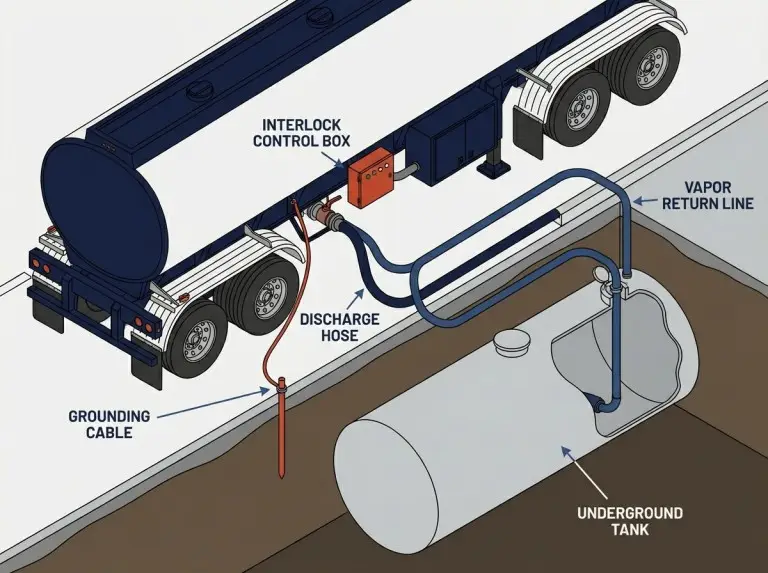
Vapor Recovery and Grounding
Both functions protect against fire and emissions. But their scope changes with the product, facility type, and local rules.
Vapor Recovery:When gasoline leaves the trailer, vapor fills the space in the receiving tank. At sites above certain volume thresholds, 40 CFR 63 Subpart CCCCCC requires Stage I vapor controls during unloading. Many states add tighter rules. These may include closed-loop vapor return and sealed connections. Rules may also require fill pipes within 6 inches of the tank bottom and back-pressure caps during transfer. Diesel and other low-vapor fuels face fewer vapor rules in most areas. We set up vapor plumbing based on the operator’s fuel mix and delivery market rules.
Grounding and Bonding:NFPA 77 and API RP 2003 set the basis for grounding during fuel transfer. Before any valve opens, a bonding cable must link the trailer frame to the facility ground point. Fuel flowing through hoses builds static charge fast enough to ignite petroleum vapor in milliseconds. Scully-type interlocks check bonding strength before they allow valve operation. This grounding step is one of several critical checks covered in our guide on how to safely operate a fuel tanker trailer.
Specify these two functions as one system. Designing them apart creates gaps. A ground interlock that skips vapor recovery status leaves a gap. A vapor line without relief valves creates risk that neither system covers alone.
Inspection, Testing, and Maintenance
Maintenance runs on two tracks: the federal minimum under 49 CFR 180.407, and the operator’s own plan based on use.
Federal Minimums:DOT 406 tanks in petroleum service need external visual checks and leak tests at the intervals in the 180.407 table. For most non-insulated tanks, that cycle is one year. Internal checks and pressure tests follow a longer cycle, usually five years. A tank out of hazmat service for a year or more must pass a pressure test. Only then can it go back on the road. After any valve, hose, pipe, or fitting repair, the part must pass a leak test before service. These are federal floors. State or carrier rules may be tighter.
Use-Based Checks:Valve seals and seats wear the fastest. Wear rate depends on fuel type, heat, and how often the valve cycles. High-use fleets in hot climates should check seals more often than the yearly federal floor. For a full breakdown of scheduled and preventive checks across the entire trailer, see our guide on fuel tanker trailer maintenance tips.
Check discharge hoses for external damage and fitting condition before each trip. Liner separation inside the hose can choke flow without showing on the outside. Test hoses at the maker’s stated intervals.
PTO pump systems need seal, bearing, and coupling checks. Flow drops as clearances open up inside the pump. Without regular flow tests against a known baseline, the drop goes unnoticed until load times rise.
Test grounding cables for electrical continuity, not just visible damage. A worn cable with high resistance may look fine but fail to clear a static charge.
Specifying a Discharge System for Your Fleet
The right spec must match the operator’s fuel mix, route, site conditions, and regulatory picture. Before placing an order, confirm these inputs:
- Fuel list with thickness range and temperature basis
- Site survey for each stop: tank type (underground vs. above-ground), inlet height, coupling type, hose run distance, vapor recovery status
- Federal, state, and local rules at each delivery point
- Target flow rate and max offload time per compartment
- Metering needs for custody transfer or fiscal records
- Tractor PTO spec if a pump is needed
| Method | Best For | Key Variables | Check Before Signing Off |
|---|---|---|---|
| Gravity | Underground tanks at retail stations | Hose ID (4 in. typical), hose length, height gap, fuel thickness | Will not work if the receiving inlet sits at or above the trailer outlet |
| PTO pump | Above-ground tanks, long runs, thicker fuels | Pump GPM, PTO fit, pipe/hose size, thickness range | Adds 200–425 lb; must fit real conditions across the full route |
Conclusion
A fuel tanker discharge system links many variables. Product type, compartment layout, valve design, pump choice, hose size, vapor recovery, and rules across the route all connect. No single default works for every case.
At Truckman Automobile, we spec discharge systems as part of the full trailer engineering review. The best setups come from a thorough pre-build look at actual delivery conditions. We confirm the fuel list, check each receiving site, and verify DOT, EPA, and state rules. We then size every part against the operator’s targets before we lock the spec. When this step gets skipped, we see trailers that work at some stops but cause problems at others. This happens most when routes mix underground and above-ground tanks. It also shows up when the fuel slate shifts after the trailer hits the road.
To start, map your delivery route and note each site’s tank type, coupling, and regulatory status. Then share those details with our team. We match the discharge system to your real conditions. We confirm that every part meets both the rules and your performance targets.
FAQ
Does every fuel tanker need a pump?
No. Trailers that only deliver to underground tanks with enough drop below the outlet can use gravity. Whether you need a pump depends on tank positions across the route and target offload time. Fuel thickness at the coldest working temperature also matters.
What makes discharge slow even with a good pump?
A bottleneck elsewhere in the system. Tight manifold piping, partly open valves, and long or narrow hoses all limit flow. Small-bore fittings and high back-pressure do the same. Rated flow only works when every part of the path supports it.
How does compartment shape affect discharge?
Slope toward the outlet, sump depth, and baffle placement all change drain speed and completeness. Flat compartments with little slope hold more leftover fuel. Set the slope angle, sump size (4-inch TTMA standard), and baffle cuts during trailer design.
What are the federal inspection cycles for DOT 406 tanks?
49 CFR 180.407 sets external visual and leak test intervals in its compliance table. Internal checks and pressure tests run on a longer cycle. A tank out of hazmat service for a year or more must pass a pressure test first. Check the current 49 CFR Part 180 for exact intervals.
Does every discharge need vapor recovery?
No. Federal rules under 40 CFR 63 Subpart CCCCCC cover gasoline sites above certain volume thresholds. States may add more rules. Diesel and other low-vapor fuels face fewer requirements, though local rules may still apply.