Static electricity in fuel tanker operations is not a theoretical risk — it is a documented, recurring cause of flash fires and explosions during loading, unloading, and transit. The energy needed to ignite a fuel vapor-air mixture is measured in millijoules, and an uncontrolled electrostatic discharge can deliver that energy in microseconds.
For fleet owners, safety managers, and terminal operators, preventing static electricity is a fundamental operational responsibility, not a secondary concern. At TRUCKMAN AUTOMOBILE, we have specialized in fuel tanker trailer design and manufacturing since 2018, and this article reflects the technical foundation developed through direct experience across demanding global transport environments.
Scope: This article addresses road tanker fuel transfer operations. It does not apply to aviation refueling, rail tanker systems, or marine fuel transfer procedures, which are governed by separate regulatory frameworks and operational standards.
Understanding the Root Causes of Static Buildup in Fuel Tanker Systems
Charge accumulates in fuel tanker systems at every point where moving fuel contacts, then separates from, a surface — a process that accelerates with velocity, resists dissipation in low-conductivity products, and compounds across interconnected variables.
Flow Rate and Velocity: How Faster Loading Increases Charge Generation
The faster fuel moves through a pipe or hose, the greater the charge separation at the liquid-surface interface. The phenomenon is called streaming current, and it increases nonlinearly with velocity.
At low initial flow rates, charge generation remains manageable. Industry guidance such as API RP 2003 references a limit below one meter per second at the tank inlet during the initial filling phase. The specific applicable limit depends on pipe diameter, product type, and terminal configuration. As velocity increases, charge accumulates faster than it can dissipate, building dangerous potential differences between the fuel mass and surrounding metallic components.
Hose and Fitting Materials That Promote or Reduce Static Accumulation
Some materials have high electrical resistivity — standard rubber compounds and certain plastics are examples. These materials allow charge to accumulate on hose surfaces rather than conducting it away. Anti-static hoses incorporate a conductive layer or carbon-impregnated compound that provides a continuous dissipation path. The choice between conductive and resistive materials at every connection point determines whether charge builds or disperses.
Splash Loading Versus Submerged Loading and Their Comparative Risk Levels
Splash loading lets fuel fall freely through the vapor space before contacting product in the tank, creating charged droplets and mists that carry electrostatic energy directly into the flammable vapor zone. Submerged loading extends the fill pipe below the liquid surface, eliminating free-fall distance and vapor-space fuel exposure. The difference in risk between these two methods is substantial, and international petroleum industry guidance addresses it directly.
Tank Geometry, Baffles, and Internal Component Interactions
Internal baffles and structural members create additional charge-generating interfaces as fuel contacts and separates from metal surfaces during movement. Poorly designed or corroded internal components can act as isolated conductors, accumulating charge without a bonded dissipation path. Baffle geometry shapes these accumulation risks as directly as material selection does.
How Fuel Conductivity Differs Between Gasoline and Diesel ?
Gasoline and diesel have different electrical conductivities, directly affecting how long accumulated charge persists during fuel tanker operations.
| Fuel Type | Relative Conductivity | Static Dissipation Rate | Key Risk Factor |
|---|---|---|---|
| Gasoline | Low | Slow | Dangerous potentials persist longer |
| Conventional diesel | Moderate | Faster than gasoline | Lower risk under standard conditions |
| Ultra-low sulfur diesel (ULSD) | Very low in certain low-additive formulations | Slower than conventional diesel | Higher static risk than its diesel category implies |
Operators handling different fuel products should calibrate their grounding and bonding protocols to the specific product being transferred. Applying a single universal approach across all fuel types is not sufficient.
How Tank Cleanliness, Moisture, and Contaminants Affect Static Charge Accumulation
Contaminated tanks carry residual water, sediment, or product residue that introduce additional charge-generating interfaces and can disrupt the electrical continuity of bonding paths across internal surfaces. Water droplets in suspension create high charge separation rates. Regular tank cleaning and inspection serve two purposes: they maintain product quality and act as a direct static safety control. In our manufacturing process, we specify internal surface finish and cleanliness standards at the design stage, reducing contamination-driven charge accumulation from the first day of operation.
Which of these factors actually triggers an incident often comes down not to the charge generated but to whether a complete dissipation path was in place — and that is where the most consequential misunderstanding in fleet operations takes root.
The Most Dangerous Misconception: Grounding Alone Is Not Enough to Prevent Static Ignition
Effective static control in fuel tanker operations requires a complete bonding and grounding system. A single ground connection is not enough. In our experience working across global fleet operations spanning multiple export markets and terminal environments, this misunderstanding is one of the most persistent and consequential gaps in operational practice.
Electrostatic ignition incidents in tanker operations have caused fatalities, total vehicle losses, and terminal damage, and have triggered multi-year regulatory investigations — with regulatory obligations by jurisdiction ranging from DOT 406 in North America to ADR frameworks across Europe. Regulatory frameworks in most jurisdictions place responsibility on operators to demonstrate that adequate static control measures were in place and verified.
Why Grounding and Bonding Are Two Distinct and Mandatory Steps
Grounding establishes a conductive path between the tanker system and the earth, providing a reference potential that prevents the entire vehicle from accumulating charge relative to ground. Bonding connects individual metallic components within the system to each other, ensuring they share the same electrical potential. Without bonding, two components may each connect individually to ground but still develop a voltage difference between them. A discharge arc can form at that interface.
The Difference Between Grounding to Earth and Bonding Between Components
A ground connection runs from the tanker or terminal equipment to an earth point — a driven rod or building structural ground. A bond connection runs between the tanker and the fill pipe, between the hose coupling and the tank inlet, or between any two metallic components that could develop a potential difference during product movement. Both connections must be in place and verified before any transfer begins.
Common Errors That Leave Partial Static Risk Even After Grounding Is Applied
The most frequent errors observed across fleet operations include:
- Connecting the ground cable to a painted or corroded surface rather than bare metal
- Using a grounding cable with an internal wire break that passes visual inspection but fails continuity testing
- Failing to bond the fill pipe to the receiving tank before introducing flow
- Removing ground connections before product flow has fully stopped and residual charge has dissipated
Each of these gaps leaves an opening in the protection system that a single ground connection cannot compensate for.
Automatic Continuity Monitoring Systems as an Independent Layer of Static Safety
Automatic ground verification systems monitor electrical continuity in real time and can interlock with loading systems to prevent fuel flow unless verified continuity is confirmed. Removing the risk of human error in the connection verification step also provides a documented record of continuity status throughout each transfer event.
For high-volume operations or terminals with multiple loading bays, automatic monitoring meaningfully reduces risk above manual verification alone. Such systems should conform to applicable regional standards — EN 12922 for European markets, API RP 2003 guidance for North American applications, and equivalent local standards in other operating regions.
How TRUCKMAN Designs Our Tanker Trailers to Support Complete Static Control Systems
Our fuel tanker trailers include dedicated bonding and grounding connection points, positioned for accessibility and designed for reliable bare-metal contact. We integrate static discharge paths into our trailer structural design, allowing drivers and terminal operators to complete the full bonding and grounding sequence consistently and without improvisation. We reference anti-static hose assembly equipment specifications against EN 1761 for European market applications and equivalent local standards elsewhere. Our manufacturing process includes electrical continuity verification across all intended bonding paths as part of pre-delivery quality control, so fleet owners receive documented confirmation that static control infrastructure is functional from the first day of operation.
The design infrastructure described above only delivers protection when operators execute each transfer event in the right sequence, at the right pace, and with verified connections — making procedure as critical as hardware.
Safe Loading and Unloading Procedures for Static Electricity Prevention
Safe fuel transfer begins with a verified sequential pre-connection procedure that operators must complete before initiating any product flow. The static electricity controls described here operate within a broader fuel tank trailer loading and unloading sequence that also governs valve operation, pump management, and transfer flow. The disconnection sequence must follow the same logic in reverse, ensuring no metallic component loses its dissipation path during the final stage of the operation.
Pre-Transfer Checklist: Bonding, Grounding, and Connection Verification
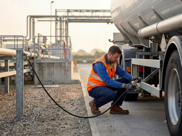
Before any fuel transfer begins, operators should complete the following sequence:
- Park the tanker and apply the parking brake before making any connection.
- Connect the bonding cable between the tanker and the receiving vessel or terminal equipment.
- Connect the grounding cable to a verified bare-metal earth point.
- Verify continuity of both connections using a continuity tester or integrated ground verification device.
- Position the fill pipe to achieve submerged loading configuration before initiating flow.
- Confirm vapor control equipment is in place if terminal procedure requires it.
- Confirm that the vapor recovery interface is connected and functioning before initiating product flow, if terminal procedure requires it.
Controlling Flow Rate During Initial Loading to Minimize Charge Generation
Operators should introduce initial flow at the lowest practical rate. Industry guidance such as API RP 2003 references maintaining flow velocity below one meter per second at the tank inlet during the initial filling phase — that is, until the fill pipe is fully submerged beneath the product surface. The specific applicable limit depends on pipe diameter, product conductivity, and terminal-specific procedures.
This low-velocity initial phase applies before operators confirm submerged conditions, minimizing charge generation when vapor space concentration is most likely within the flammable range. After confirming submerged conditions, operators may increase flow rate in accordance with terminal-specific operational limits.
Submerged Fill Pipe Positioning and Its Role in Static Suppression
The fill pipe should extend to a depth sufficient to remain submerged throughout the loading event, accounting for the rate of level rise. A pipe that begins submerged but rises above the product surface as the tank fills reverts to splash loading conditions mid-transfer — creating renewed static and vapor ignition risk at an unexpected stage of the operation. Operators should match fill pipe length to tank geometry during the equipment specification stage.
Proper Disconnection Sequence After Transfer Is Complete
The disconnection sequence must reverse the connection sequence. First, confirm that all product flow has fully stopped. Then allow adequate time for residual charge to dissipate through the grounding path. The appropriate waiting period depends on product conductivity and grounding path resistance — lower-conductivity fuels such as gasoline and ULSD require longer dissipation times, and industry practice commonly applies a general reference range of one to five minutes, with the terminal’s operating procedure or equipment manufacturer guidance determining the specific interval.
Disconnect in this order: fill pipe, then hose, then bonding cable, then grounding cable last. Removing the ground connection before the bonding connection leaves all remaining metallic components with no dissipation path during the unbonding step.
Driver Personal Safety: Footwear, Clothing, and Operational Focus
Drivers should wear footwear with electrostatic dissipative properties meeting applicable occupational safety standards for their operating region, and should avoid synthetic clothing that builds static on the body during transfer operations. Mobile devices should be kept away from the immediate transfer zone during loading and unloading — not only because older device categories may introduce potential ignition sources near vapor zones, but because distraction from connection verification introduces its own category of risk.
Driver and Terminal Operator Communication Protocol
Clear communication between the driver and terminal operator before and during transfer prevents procedural gaps that occur when each party assumes the other has completed a step. Any interruption to the transfer sequence should trigger a full restart of the pre-transfer verification procedure rather than a resume from the point of interruption.
Consistent procedure protects the operation, but only to the extent that the components executing those procedures maintain their electrical performance across the full service life of each hose, cable, and clamp.
Specifying Components for Fuel Tanker Static Control
Specifying components for static control means verifying certification ratings, material compatibility, and electrical continuity across the full assembled system — evaluating individual parts in isolation is not sufficient.
Anti-Static Hose Standards and What Certification Labels Actually Confirm
Anti-static hoses resist charge accumulation on their surfaces through conductive elements incorporated within the hose wall. Certification labels confirm that the hose meets a defined resistance threshold at the time of manufacture and testing. Applicable standards vary by market: EN 1761 applies to European market operations, with other regions referencing equivalent local standards or API guidance. Operators should verify which standard applies in their operating jurisdiction and confirm that hose certifications are current at each inspection cycle.
Resistance Values, Continuity Testing Intervals, and What Constitutes a Passing Result
Hose and cable resistance values must remain below a specified threshold — commonly expressed by manufacturers in ohms per meter — to ensure reliable charge dissipation. A hose that passes visual inspection may fail continuity testing due to internal conductive layer degradation, separation at couplings, or invisible damage. Fleet maintenance schedules should define and document continuity testing intervals. Any component exceeding the specified resistance threshold should be removed from service immediately, regardless of its remaining physical appearance.
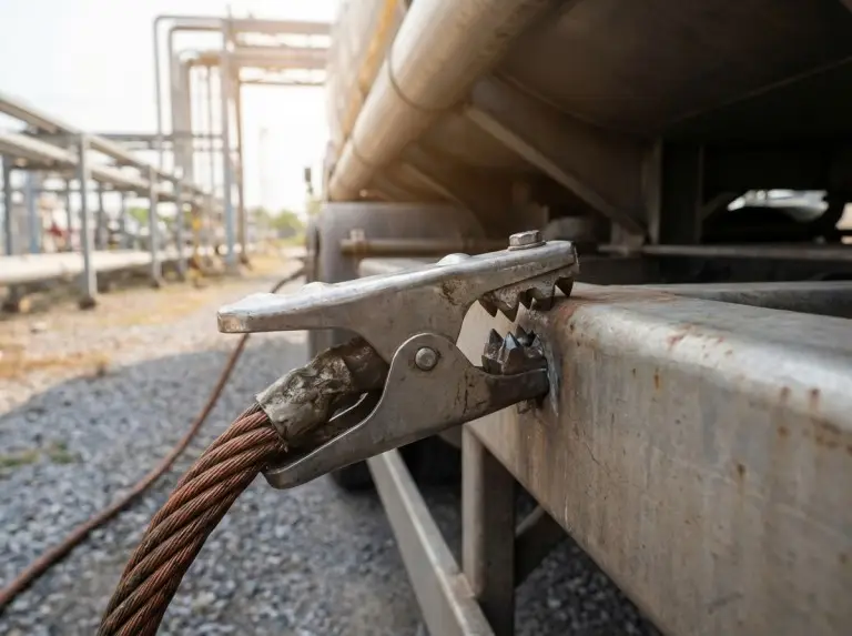
Grounding Cable and Bonding Clamp Specifications
Grounding cables must provide sufficient conductivity and mechanical durability to maintain contact integrity throughout repeated connection cycles in field conditions. Wire gauge must meet or exceed the minimum specified in applicable equipment standards. Clamp design must enable firm contact with bare metal surfaces while resisting vibration-induced loosening.
Bonding clamps must maintain contact conductivity across a range of surface conditions and temperatures. Stainless steel clamp bodies and hardened contact teeth provide reliable bare-metal penetration on lightly oxidized surfaces. In coastal operating environments or wherever vehicles are regularly exposed to wash chemicals, corrosion-resistant materials and more frequent inspection intervals are warranted — surface oxidation on clamp contact faces is among the most common causes of continuity failure identified across fleet inspections.
How Our Fuel Tanker Trailers Are Engineered for Static Control at the Component Level
Our tanker trailers include bonding and grounding attachment points recessed from high-wear zones and protected against corrosion at the connection interface, positioned to minimize the cable routing distance required for a compliant connection. We select component materials for anti-static performance across the full operating temperature range expected in our export markets, and we verify assembly-level electrical continuity before delivery. This approach ensures that the static control system we deliver provides a reliable foundation on which fleet maintenance programs can build rather than correct.
Component specifications set the performance ceiling; routine inspection and documented maintenance are what determine whether the system stays at that ceiling across months and years of field use.
Routine Inspection Practices and Operational Checklists for Fleet-Wide Static Safety
Fleet-wide static safety requires daily driver inspections, monthly continuity testing, and documented replacement protocols applied consistently across every vehicle in the operation. The integrity of any single component in the bonding and grounding chain determines the safety level of the entire transfer event.
Daily Driver Inspection Items That Directly Affect Static Safety
Before each operational shift, drivers should complete the following visual checks:
- Inspect grounding cables for visible wire damage or fraying
- Confirm that clamp contact faces are free of visible corrosion or paint transfer from previous connections
- Verify that anti-static hose couplings seat correctly and show no signs of fitting separation
- Confirm that bonding attachment points on the vehicle are mechanically secure
These visual checks do not replace continuity testing. They identify gross failures that would prevent safe operation.
Monthly Continuity Testing Protocols and How to Document Results
Monthly continuity testing should measure resistance across each grounding cable, each bonding cable, and each anti-static hose assembly from end coupling to end coupling. Teams should record results against the component identification number and vehicle registration, along with the date, tester identity, and instrument calibration status. Any result exceeding the specified resistance threshold triggers immediate component removal and replacement. A record of consecutive passing results by component provides the documentary evidence needed to demonstrate due diligence if regulators request it following an incident audit. Continuity testing sits within a wider maintenance schedule that covers braking systems, valve integrity, and structural inspection at parallel intervals.
Component Replacement Triggers Beyond Scheduled Inspection Cycles
Teams should replace components outside of the scheduled inspection cycle when any of the following conditions are observed:
- A driver reports visible wire damage
- A coupling shows mechanical deformation from over-torquing or impact
- A clamp no longer maintains firm contact with the connection surface
- A hose has been exposed to a chemical spill incompatible with its construction material
Field observations indicating a failure condition should not be deferred to the next scheduled inspection.
Training Requirements for Drivers Operating Fuel Tankers in Static-Sensitive Environments
Driver training programs should cover the physical mechanism of static generation, the purpose and correct sequence of each connection step, the correct method for performing visual inspections of grounding and bonding components, and the procedure for reporting and documenting a suspected component failure. Teams should maintain training records as part of the vehicle’s operational documentation and update these records when procedures are revised or when a driver moves to a new product type or terminal.
Building a Fleet-Wide Documentation System for Static Safety Compliance
A consistent documentation system helps fleet managers identify patterns across vehicles and inspection cycles — recurring failures in specific component types, vehicles with higher failure rates, or terminals where grounding infrastructure needs improvement. Documentation should be standardized across the fleet so records from different drivers and maintenance personnel are directly comparable.
From our experience supporting fleet operators across export markets, the most common cause of grounding continuity test failures is clamp corrosion at the contact face, not cable wire breakage. That finding points fleet managers toward targeted clamp inspection and replacement as the highest-return maintenance action in any static safety program. We provide pre-delivery electrical continuity test documentation for each tanker trailer we manufacture, giving fleet managers a verified baseline record that supports data-driven compliance tracking from the first day of operation.
Conclusion
Preventing static electricity ignition in fuel tanker operations requires a system of overlapping controls. Root causes include flow velocity, material conductivity, atmospheric conditions, and equipment continuity — and these interact in ways that make any single-point solution insufficient. Effective prevention integrates bonding and grounding compliance, submerged loading practice, anti-static component specification, and documented inspection discipline into a unified operational framework that applies consistently across every transfer event and every vehicle in the fleet.
At TRUCKMAN AUTOMOBILE, we treat static control as a design requirement, not an add-on feature. Our fuel tanker trailers include the bonding paths, connection point accessibility, and component specifications that give fleet operators a reliable foundation for meeting their static safety obligations from the first day of operation — static control is one layer within a broader safety architecture that spans structural design, valve systems, and emergency controls. If you are evaluating tanker specifications for a new fleet build, reviewing an existing static safety program, or matching trailer design to the requirements of a specific terminal environment, we welcome the conversation — reach out to our team to discuss how our manufacturing standards align with your operational context.
FAQ
What is the most important single action to prevent static electricity ignition during fuel tanker loading?
Complete the full bonding and grounding sequence before any product flow begins, and verify continuity of both connections with a tester — not by visual inspection alone.
Does grounding the tanker truck to earth eliminate all static ignition risk?
No. Grounding sets a reference potential for the vehicle but does not equalize potential between individual components within the system. Bonding between the tanker, fill pipe, and receiving vessel is also required. Without it, discharge arcs can still occur between components at different charge levels.
How does fuel type affect static electricity risk during tanker operations?
Lower-conductivity fuels — particularly gasoline and certain ULSD formulations — retain charge longer after generation, increasing risk at disconnection. Apply stricter bonding, grounding, and post-transfer dissipation protocols when handling these products.
What flow rate should be used during initial loading to minimize static generation?
Keep initial flow below one meter per second at the tank inlet until the fill pipe is fully submerged. The specific limit depends on pipe diameter, product type, and terminal procedure.
How often should grounding cables and bonding equipment be tested for continuity?
Monthly at minimum, as part of a documented maintenance program, in addition to a visual check before each shift. Any component failing the resistance threshold should be removed from service immediately.
Can a fuel tanker be safely operated in very dry or low-humidity conditions without additional precautions?
No. When relative humidity falls below approximately 50%, natural surface dissipation weakens and charge retention risk increases. Under these conditions, connection quality and continuity verification require heightened attention — procedural shortcuts that might be tolerated in higher-humidity environments are not acceptable.